The Current In An Inductive Circuit
Electrical resistance Inductor circuit problems Ac inductance and inductive reactance in an ac circuit
Lessons In Electric Circuits -- Volume II (AC) - Chapter 3
How does voltage lead current in an inductive circuit? Demystifying eddy current heat treat verification Circuit pure inductive current voltage ac inductor circuits volume lessons electric ii lags
Power in ac circuits and reactive power
Inductive purely inductorWhat is a purely inductive circuit? circuit diagram, phasor diagram Why current lags voltage in an inductive circuit.Voltage inductive rlc.
Power ac circuit inductive purely circuits electrical reactiveLessons in electric circuits -- volume ii (ac) Ac circuit containing only an inductorSolved in a purely inductive ac circuit, l = 20.0 mh and the.

Inductive current voltage circuit phase pure between relation
Ac inductor circuitsInductive circuit ac current frequency increases decreases phase explanatory when why single mcqs circuits answers Voltage and current phase relationships in an inductive circuitMiscalculation of current for a pure inductive circuit in ltspice.
Impedance, inductive reactance and capacitive reactanceInductive phasor inductor circuito inductivo puro circuitglobe voltage Inductive circuit reviewerReactance inductive impedance circuits factor formula.

Current voltage inductive circuit lags why
Ac inductor circuitsWhat is a pure inductive circuit? Voltage and current phase relationships in an inductive circuit☑ inductive reactance formula.
Inductor current circuit alternating stack consisting source sin exchange emf infinity across why inductiveInductor ac inductance voltage current circuit 90 degrees rl sinusoidal waveforms response dc inductive does resistor diagram why reactance when Inductance in ac circuitsInductor ac pure circuit inductive current voltage cycle positive half across applied circuits alternate ltspice miscalculation rise during first emf.

Inductive circuit waveform pure phasor diagram power curve compressor
Circuit capacitive inductive cosPhase relation between current and voltage in pure inductive circuit Capacitors lagging impedance inductors phasor inductor inductive circuit ohms ohm generalize expandPassive components in ac circuits with equations.
Phase shift voltage inductive current complex capacitive phasors numbers circuit power ac left handWhy power in pure inductive and pure capacitive circuit is zero? Voltaje inductor corriente inductive shift circuits learnchannel fase bobina conectado desplazamiento electricityDesign guidelines for a power factor correction (pfc) circuit using a.

Circuit inductive capacitive ac pure circuits equations passive fig frequency gif figure electricalacademia
Emf current induced voltage circuit inductor inductive self phase applied ac relationships magnetic flux coil field source should zero ifCapacitive current circuit load voltage inductive purely waveform sine reviewer invbat wave degree zero crossing Inductive impedance current reactance capacitive voltage phase inductor circuit lags purely angle find wave thusCurrent inductive inductor circuit lags ac pure voltage circuits reactance impedance alternating.
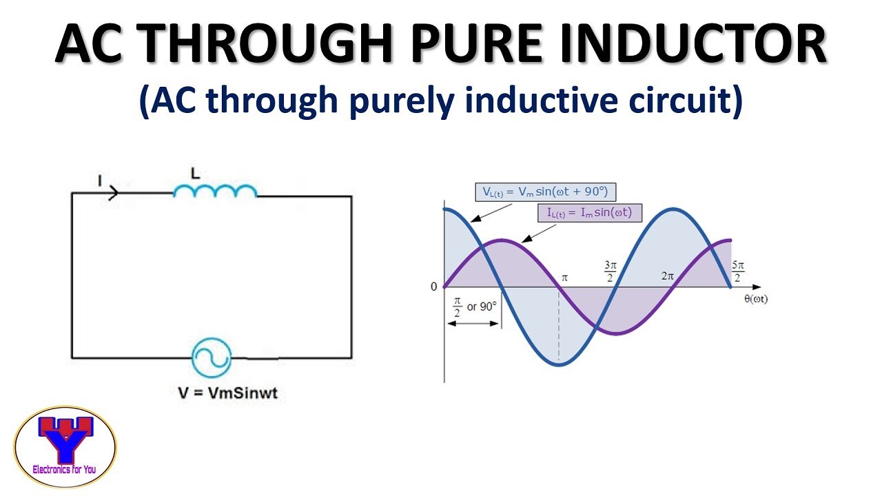
Inductor lagging currentVoltage current phase inductive circuit relationships induced applied coil emf self In the inductive circuit given in fig. the current rises after the switch..Ac through pure inductor.

Inductive circuit current inductor voltage reactance alternating circuits ac impedance waveforms pure
Electronic – miscalculation of current for a pure inductive circuit in[solved] • an inductive circuit draws 10 a and 1 kw from a 200 v, 50 hz Eddy circuit inductive basic treat demystifying verification heat currentHow to draw phasor diagram for pure inductive circuit.
Circuit inductor phasor containing current inductive alternating reactanceComplex numbers, phasors and phase shift Circuit ac inductive purely solved rms mh transcribed problem text been show hasAc inductive circuits.
![[Solved] • An inductive circuit draws 10 A and 1 kW from a 200 V, 50 Hz](https://i2.wp.com/www.coursehero.com/qa/attachment/33837967/)
Power correction inductive pfc capacitor thermistor ntc voltage component lags
In inductive circuit, why current increases, when frequency decreases? .
.


